


How does a flyback transformer work?
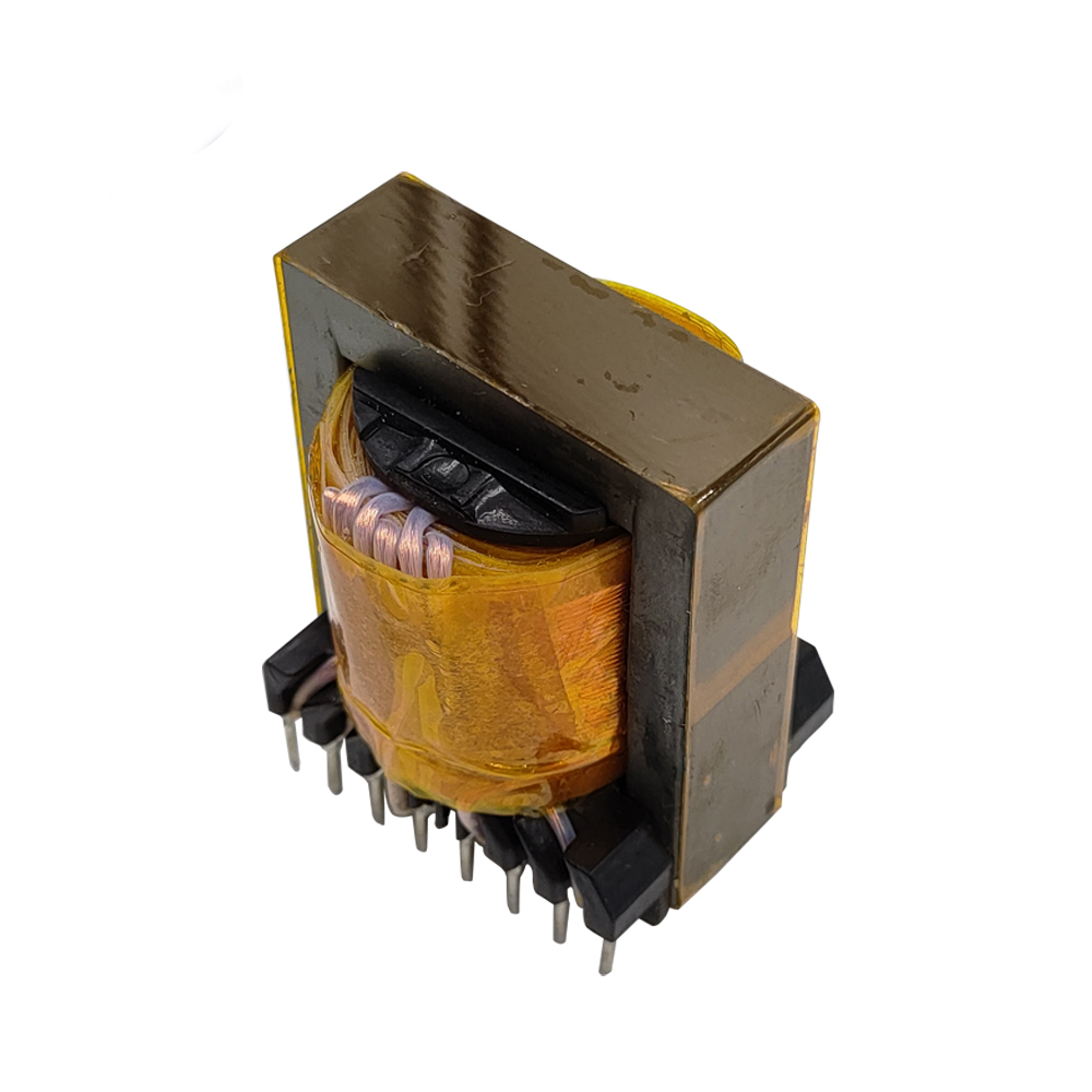
A flyback transformer, also known as a line output transformer, is a special type of transformer used primarily in flyback converters, which are a type of switch-mode power supply (SMPS). The flyback transformer is designed to store energy when the input switch is on and to release this energy to the output when the switch is off. Here’s a detailed explanation of how a flyback transformer works:
Basic Operation
-
Switch On (Energy Storage Phase):
- When the switch (typically a transistor) connected to the primary winding of the transformer is turned on, current flows through the primary winding.
- This current creates a magnetic field in the core of the transformer, and energy is stored in this magnetic field.
- During this phase, the voltage across the secondary winding is such that the output diode is reverse-biased, and no current flows to the load.
-
Switch Off (Energy Transfer Phase):
- When the switch is turned off, the current in the primary winding stops suddenly.
- The magnetic field in the core collapses rapidly, inducing a high voltage in the secondary winding.
- This induced voltage in the secondary winding is now forward-biased for the output diode, allowing current to flow through the diode to the output capacitor and load.
- The energy stored in the magnetic field is thus transferred to the load.
Key Features and Components
- Primary Winding: Connected to the input power source through a switching element (like a transistor).
- Secondary Winding: Connected to the output circuit, which includes a diode and a capacitor to rectify and smooth the output.
- Core: Typically made of ferrite, designed to store energy during the switching cycle.
- Switching Element: Usually a transistor that controls the current flow through the primary winding.
- Diode: Ensures that current flows only in the correct direction to charge the output capacitor.
- Output Capacitor: Smooths the rectified voltage to provide a stable DC output.
Flyback Converter Circuit
A typical flyback converter circuit consists of the following stages:
- Input Stage: An input filter to smooth out any incoming voltage ripple.
- Switching Stage: A transistor (like a MOSFET) that switches the primary current on and off.
- Flyback Transformer: With primary and secondary windings to transfer energy.
- Rectification Stage: A diode connected to the secondary winding to rectify the induced voltage.
- Output Stage: A capacitor to smooth the rectified voltage and provide a stable DC output.
Advantages of Flyback Transformers
- Isolation: Provides electrical isolation between input and output, which is important for safety.
- Wide Range of Output Voltages: Can provide multiple output voltages by using multiple secondary windings.
- Compact Design: The transformer can be relatively small compared to other types of transformers for the same power rating.
- Efficiency: Efficient at converting power, especially in low to medium power applications.
Applications
- Power Supplies: Used in AC-DC and DC-DC converters for devices like laptops, TVs, and other consumer electronics.
- Telecommunications: Power supplies for telecom equipment.
- Industrial Electronics: Used in various control systems and instrumentation.
Summary
A flyback transformer works by storing energy in its magnetic core when the input switch is on and releasing this energy to the output when the switch is off. This allows for efficient energy transfer and voltage conversion, making it ideal for use in switch-mode power supplies. The flyback transformer's design enables it to provide electrical isolation and accommodate a wide range of output voltages.